I wanted:
a) - drawers accessible from the front
b) - shelf above main deck for commonly used things
c) - a deck to support the lathe, with enough room for accessories
d) - the deck needed to be thick enough for drilling and tapping into
e) - the deck needed to be magnetic (for DTI bases)
f) - the deck needed to have a raised edge so things couldn't fall off it
g) - preferably no "traps" for swarf to build up in
h) - a way to easily remove swarf
i) - motor mount which permitted unloading of belt
j) - accessible power points
k) - variable speed motor
l) - reversing motor
m) - task lighting
n) - controls accessible without reaching through rotating parts
o) - cabinet wired as an "appliance"
Points J to O are basically electrical in nature and influenced the electrical design.
The electrical design was done with a sketched up line drawing based on the salvaged parts I had (from some scrapped switching machines)

Figure 1 - Hand drawn schematic of circuit
Whilst building the cabinet, I used a hand drawn schematic, but then once completed, I drew it up properly (Paint then exported to jpg) for the "point to point" testing.
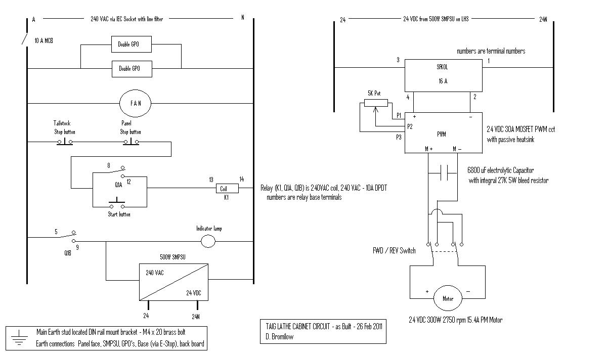
Figure 2 - Schematic done to a more professional standard
The variable speed motor was accomplished with the use of a Pulse Width Modulated (PWM) controller, with a large (6800uF electro) capacitor added for smoothing - subsequent discussion on aus.electronics demonstrated that this smoothing cap should not be added, so it was subsequently removed. I added a 20A DPDT toggle switch for accomplishing the reversing function.
The mains voltage design started with a IEC socket (with line filter) which is switched through a 10A MCB (miniature circuit breaker). The circuit supplies a pair of double GPOs, and a fan which pulls air into the control cabinet. The supply to the PSU is controlled through a 10A DPDT relay which uses latching circuitry on one set of contacts to hold the supply on to the PSU, dropping it when either "E-Stop" button is pressed. The relay pulls in if the start button is pressed, but loss of supply will release it, and restoration of supply will not automatically re-close it without another button press. This supplies the No Volt Release (NVR) functionality I wanted for safety.
Supply from the PSU is fed through a SFKOL (GE motor start over current protection device) and to the PWM speed control. The SFKOL protects the PSU from a short in the motor, cabling, or PWM circuit.

Figure 3 - Wiring commencement

Figure 4 - Wiring continued
All 240VAC wiring was done with 2.5mm2 cabling, and all 24VDC wiring done with 4mm2 cabling. I tried to maintain the wiring code relevant to Oz with respect to colours of cables, and marking of earth, etc.
The majority of cabling is contained within the control cabinet, but there is some cabling which is outside the cabinet. The motor cable, and base "E-stop" circuit are passed through the floor of the control cabinet using cable glands in a non-ferrous gland plate. Both cables have an Earth core, although the motor cable earth is not connected to anything at the motor.
The E-stop cable has a protected connection on the rear of the backboard where connection can be broken for service. The cable to the RHS base E-stop (tail stock E-stop) is routed inside the tube frame for protection, and a 5mm (3/16") thick support rod was welded into the frame to support the cable so it couldn't foul against the drawers, or the swarf gate. The support rod is shown with a light gauge test cable. The heavier (orange sheathed) cable is held in place with the support rod using cable ties (aka zip ties).

Figure 5 - Tailstock cable support rod test
The back of the tail stock E-stop is shielded by a sheet metal cover, which terminates the Earth core. Bonding of this Earth to the base frame is accomplished by the face mounting screws, and another bonded cable.
The entire lathe cabinet is technically an appliance, and as such was tested for Earth Leakage, insulation resistance, etc prior to powering on. All tests passed.
Still to be described - the panel controls and constructing the switches.

No comments:
Post a Comment