Sunday, March 13, 2011

Taig Lathe Cabinet - Motor Mount and unloader

I'll start documenting the build of the lathe cabinet using those photos still on the card in the camera (the other photos will have to wait until after the PC is rebuilt)

The Motor Mount
The original lathe stand used a jackshaft mounted on a wooden slide-way for a clutch, and speed control was limited to the cone pulleys on the motor/jackshaft - and then the standard Taig 6 speed cone pulley.

The new motor system would have the motor speed controlled by a VSD (Variable speed drive) giving infinite speed control over the range of 0-100%.
I still wanted a clutch (unloader) so I looked at various designs used by others and cobbled up a version of my own.

The belt tension aspect of the motor mount is loosely based on a design shown on Nick Carter's website. (www.cartertools.com)
His design uses rods for alignment, and a threaded rod for adjusting the position of the moving member. My design uses slots cut in the mount for alignment, and a threaded rod for adjustment.
The basic structure is made of two pieces of 50x50x3mm angle iron (2" x2" x1/8") welded together to make a channel 100mm wide and 50mm deep (4"W x 2"D). the length of the pieces is approx 200mm (8")

I then cut 2 pieces of 50x50x3mm angle iron at around 300mm (12") long and cut slots about 12mm (1/2") from one edge. The slots were a clearance fit on standard 6mm bolts. (Slots were cut using drills to mark the ends, then 1mm cutting disc in between)

Corresponding holes were drilled in the piece made earlier in the description, and 20mm (3/4") bolts were tacked into place so the threads extended out through the slots.
End pieces were measured and made up to close out the end of the longer pieces, as much for stability, but also to support the threaded rod used for the adjustment.
The moving part is driven by a nut which was threaded in, and then tack welded to the underside of the moving part.Nuts spun on to the threaded rod, and welded in place became the thrust surfaces for the rod's action, and one nut was welded in place out the front of the unit for adjustment purposes.


Figure 1 - base of motor mount - sliding parts.

The pieces already described do not actually mount the motor, instead they provide a base which can be adjusted. The part which actually supports the motor is a hinged channel (cut from the side of some 100x100x3mm square tubing) so it actually 100mmwide, and 15mm deep.
A corresponding piece is fabricated from 4mm plate to sit atop the moving motor mount part made earlier, and to support the channel piece just described. The channel piece supports the motor by means of 2 slots cut in the channel at right angles to it's long axis - these permit adjustment of the motor position along it's shaft axis.

The channel is hinged onto the mount plate, and a cam is placed near the mount hinge to change the angle of the channel. The cam was built by cutting an approximate shape from 4mm sheet, then  tack-welding a 15mm wide strip of sheet around the cam surface for wear reduction. The cam has a position where the "lifting effect" is stopped - this is the position where the motor is tilted back away from the headstock of the lathe.


Figure 2 - the built up cam which tilts the motor mount channel.


So the overall structure is:
the motor tilts forward and backward within a range of motion governed by a cam (35mm = 1 1/2")
which sits atop a sliding mechanism which adjusts belt tension over a range of 75mm (3")
The motor can also move along it's shaft axis by 25mm (1") via the slots its mounted in.

The cam is operated by a wire lever about 250mm (10") long located well out of the way on the LHS of the cabinet.


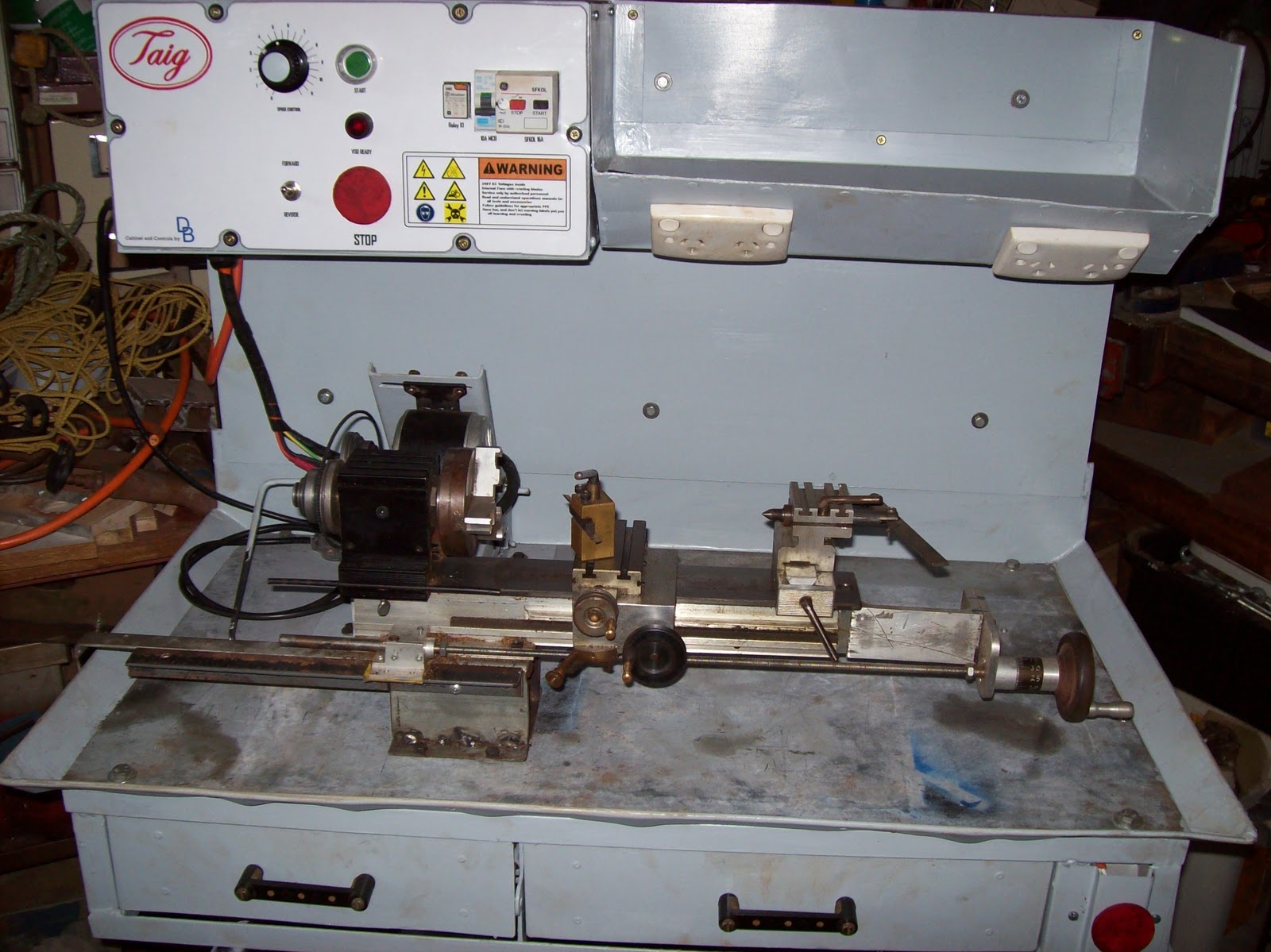
Figure 3 - completed motor mount assembly

A standard steel ruler pinched under one of the slide nuts was used to test the range of the tilt mechanism


Figure 4 - Motor mount system in the unloaded (belt tension released) position.

The recorded range of motion was approximately 35mm (1 1/2") between unloaded (no tension) to the loaded (tensioned) position.


Figure 5 - Motor Mount in the loaded (tensioned) position.

Why have the facility to drop belt tension via the lever?
#1 - ability to leave the lathe when not in use with the belt un-tensioned to prolong belt life
#2 - easier changing of positions of the belt on the 6 speed pulleys
#3 - less chance of driving the motor when moving the spindle by hand (new motor is a PM DC motor which would act like a generator if I spin the chuck by hand)

So based on this design whenever I change the belt, I would place the belt on the appropriate pulley range and push the lever up into the "loaded" position.
I would then use a 17mm socket to adjust the threaded rod and move the sliding part so the belt tension was where I wanted it.
Then I would use the lever to reduce the loading, and adjust speed ranges accordingly.

In testing, I have found the flat section on the cam is sufficient - I can "feel" it click in through the handle, and the tension stays constant during use.


Next couple of posts:
I have photos of the frame construction, basic sheet metal work, and the construction of the control panel i can access. It doesn't cover much of the control electrical system, but does cover the fabrication of the switches, and the panel-work itself.

Monday, March 7, 2011

Taig lathe cabinet - completed

Today I took advantage of some time away from work during the public holiday to bolt the Taig lathe to the new stand.

Some history...

Figure 1 - original lathe stand

I bought the original Taig lathe from an amateur pyrotechnician in Brisbane in 2001 (or was it 2000?) The motor which came with it was a salvaged unit from a washing machine.


I modified the motor mount to retain the pillow block and 1/2" shaft, but mounted the motor and jackshaft on a set of sliding mounts which gave me a clutch in the form of a "belt unloader".


Figure 2 - motor mount and jackshaft on sliding mechanism

I put a drawer underneath the 18mm (3/4") MDF top sheet and used it this way ever since. In the meanwhile a removalist broke the jackshaft mounts, the motor board started a gradual twist (compensated for by inserting popsticks under the motor mounting), and the bearings in the motor started to fail.


Figure 3 - tail stock view of old stand

The motor controls (on-off switch) is mounted in the front of the white icecream container screwed to the baseboard - inside the icecream container is the start capacitor and the wiring out to the motor. - real high tech.

Over the past 5 years I commenced modifying the lathe by adding a leadscrew and halfnuts, converting the tool post and tail stock socket screws to thumb bolts, and building accessories.


Figure 4 - the conversion of socket screws to thumb bolts

So after essentially 10 years, this 12-14 year old lathe is getting a new cabinet and drive

That was the past - now here is the future...

Figure 5 - the new cabinet with Taig lathe in place


Electrical highlights
300W DC PM motor driven via a PWM VSD (Pulse Width Modulated) (Variable Speed Drive)
NVR and E-stop safety circuitry (No-Volts Relay)
4 switched GPOs onboard


Powered from a single 240VAC IEC power cord


Figure 6 - electrical cabinet

Mechanical features
Metal cabinet with enough "meat" to permit drilling and tapping accessories anywhere I want.
Swarf tray with gate in floor
magnetic metal base for DTI, etc
motor mount has a "belt unloader"
All painted up in "Bender gray" except the 4mm thick metal baseplate

The motor mount is loosely based on the Nick Carter design, but modified for my purposes with a cam operated unloader mechanism.


Figure 7 - the motor mount in the "unloaded" position

The control panel represented an interesting amount of work which will be covered in greater detail later. one of the fun parts was the logos and labelling - the frustrating parts was doing the wiring to a suitable standard which permitted easy construction, and repairs.


Figure 8 - close up of control panel

In all, about one month's work over weekends, and the odd day here and there (mornings during shift rostered days.) - estimated total labour time would  be 100 hours
The wiring took about 3 days since I had to redo some of it when my neighbour offered some advice on how to make it better for someone else to fault find in.
Everything except the motor and some electrical components was either constructed, or salvaged - the out of pocket expenses were around $200, and a large chunk of that was for the power supply.

I will do up some articles which highlight the construction process, with focus on the various components/ skills, but in the mean time I'm going to enjoy using this "reborn" lathe.

Sunday, March 6, 2011

Making some dolls houses (CBFT training aid)

My ERT trainer mentioned once that as part of Compartment Fire
Behaviour Theory (CFBT) training, we can observe the phenomenons
(neutral plane, pyrolysis, etc) in a training aid called a "dolls house".


Figure 1 - cutting up the chipboard

A dolls house is made of chipboard and is nominally 400 x 400 x 400 mm  in size with a door way cut in one side.
The plans called for 16mm chipboard, but all the local supplier had was 18mm - no difference, just means the internal volume will be slightly less... with thicker walls the burn may take more time before the house falls apart.

Basically I cut up 2 full sheets using a circular saw, and then nailed the pieces together to hold the bits together whilst the "liquid nails" (construction adhesive) set up.


Figure 2 - the doorway cut into strips which can later be broken up as cribbing


I cut up the left over pieces to make 6 small "tables" to simulate internal furniture, and the remaining timber was cut into small pieces to kindle the internal fire ( pieces called cribbing are all about 1/4" wide, and the full 18mm thick)


 Figure 3 - open door to dolls house with "ikea table" inside


I also had to make a stand to place the completed dolls house at around chest level. I had a cast iron base from a large industrial fan which I modified to take a base for the dollshouse.


Figure 4 - completed stand with base for dolls house

During the construction of the stand, I had to undo a bolt on the stand which was slightly rusted - when the nut/bolt rust finally broke free, the spanner spun through and crushed my ring finger splitting the nail from side to side. Hurt like blue blazes, and bled like nothing I've seen in ages. After a few hours the bleeding had stopped and this is what it looked like...


Figure 5 - injury to ring finger


Job done as delivered to the trainer.


Figure 6 - completed houses and stand


Next posting/s should be the completed taig lathe cabinet, and construction articles.